3D vision · BIM automation
Scan-to-BIM: point cloud to verified IFC
A human-in-the-loop pipeline that turns a laser scan into an IFC model of slabs, walls and columns. Every element must be backed by real point support and a reviewer checks it before sign-off.
- Context
- AGECS (R&D) · contractor site scan and public benchmarks
- Period
- Jun 2026 – present
- My role
- R&D engineer: pipeline design, geometry classification, IFC generation, verification
- ~264 M
- Points in the site scan
- 7.7 GB PLY · single storey
- 2 · 9 · 21
- Slabs · walls · columns in IFC
- re-verified with IfcOpenShell
- 18.5 min
- End-to-end regeneration
- phased notebook, 0 blocking errors
- 0.92
- Column IoU (synthetic)
- PointNet++ · walls 0.89, floor 0.87
Chapter 01
The engineering challenge
Real scans are enormous: the site scan here was about 264 million points (7.7 GB). They also contain scaffolding, shoring and clutter that automatic pipelines mistake for structure.
An open-source baseline (Cloud2BIM) produced walls with the wrong orientation and forced-rectangle columns, which a reviewer rejected in ReCap.
Chapter 02
Input data
Site laser scan
~264 M points, 7.7 GB PLY, single storey (anonymised)
Public benchmark
Kladno station point cloud
Synthetic interior
207k labelled points for semantic segmentation tests
Chapter 03
The AI & engineering workflow
Stage 1 of 5
Ingest
E57 / PLY → subsample (memory-mapped, chunked)
What I did
- Adapted the open-source Cloud2BIM pipeline and kept its slab detection and IFC writer, while replacing wall and column classification with my own geometry classifier.
- Fixed a ~90° wall-orientation bug (the `minAreaRect` angle convention) and checked it against independent PCA on 9 of 9 walls.
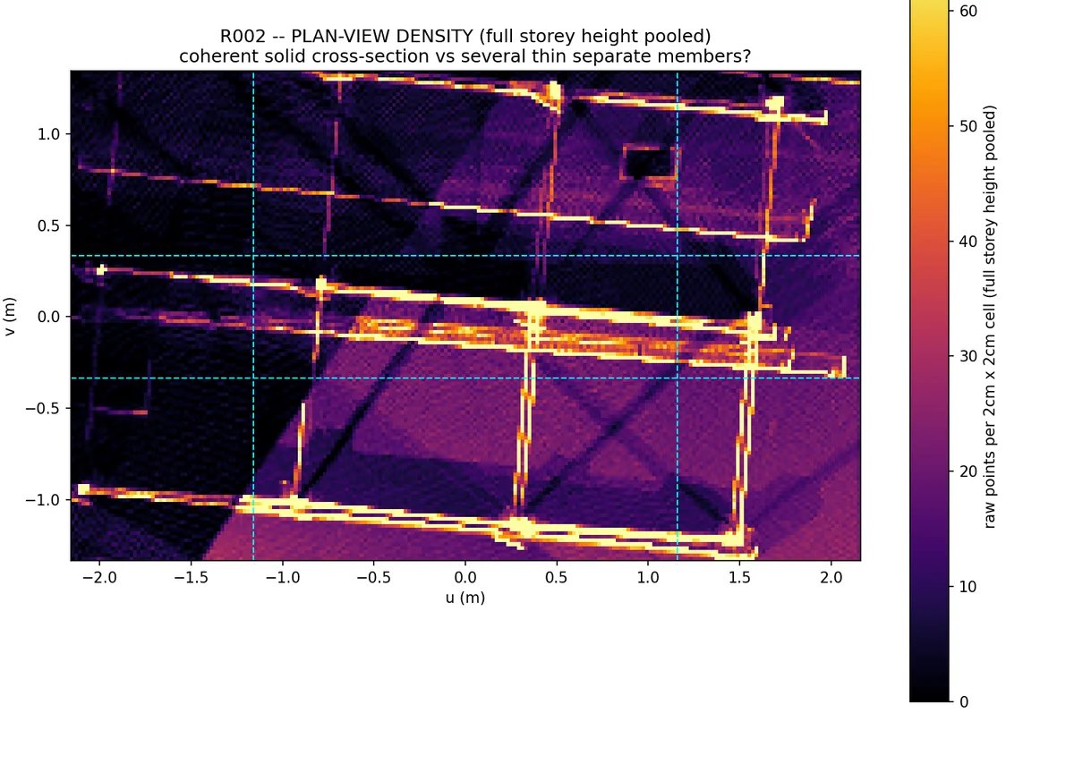
- Built a multi-blob connected-component test that rejects temporary steel props and shoring without hard-coding to the dataset (23 → 21 columns, with all confirmed elements kept).
- Wired the whole flow into a phased notebook with approval gates. It regenerates the IFC end-to-end in ~18.5 minutes, and I re-verified the output from a fresh IfcOpenShell process.
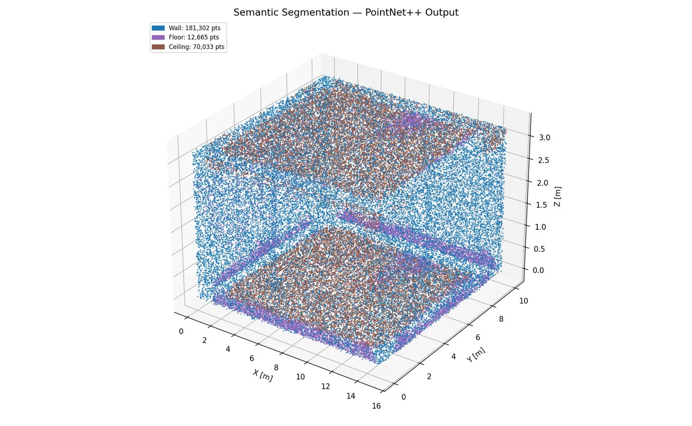
- Benchmarked PointNet++ semantic segmentation on a synthetic building interior and ran the pipeline on the public Kladno station dataset.
Real scan · real IFC
The Kladno station scan and my final IFC model.
120,000 points sampled from the 250.5 M-point benchmark scan, coloured by the IFC element they support, then the model revealed storey by storey.

Real scan (public Kladno station benchmark) and my final IFC output, shown in their shared coordinates.
Input → output
Drag to compare.
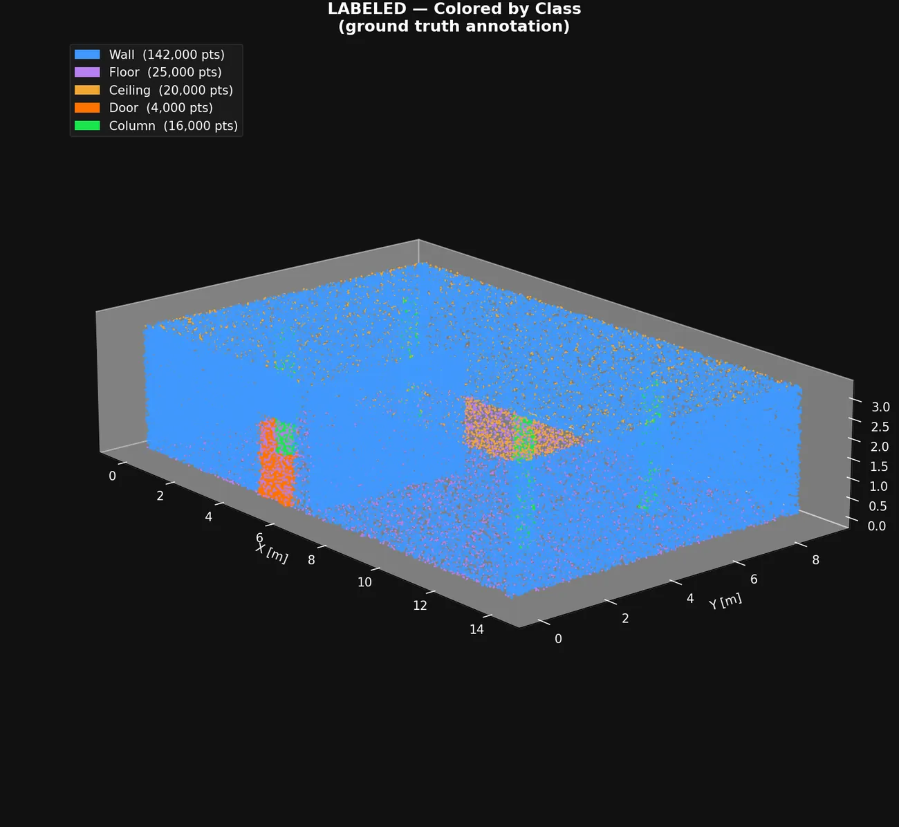
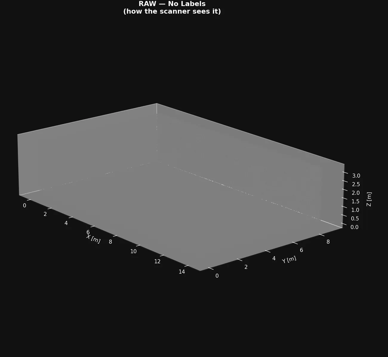
Synthetic building interior: the unlabelled scan against its class-labelled version (walls, floor, ceiling, doors, columns).
Chapter 04
Technical result
- Produced an interim IFC with 2 slabs, 9 walls and 21 columns. Each element traces to raw point support, and a fresh re-run reproduced the model exactly.
- Removed temporary shoring and a lattice fragment automatically, keeping all 12 previously confirmed permanent elements.
- Documented reusable methods: visual-first column-shape verification, and a temporary-works detection pipeline for future scans.
PointNet++ per-class IoU on a synthetic interior
Mean over the five classes present: 0.823.
The notebook's reported mIoU of 0.686 includes an empty background class scored as 0. Doors are most often confused with walls (16%).
View data table
| Category | IoU |
|---|---|
| Column | 0.922 |
| Wall | 0.888 |
| Floor | 0.874 |
| Ceiling | 0.873 |
| Door | 0.560 |
Source: AGECS PointNet++ evaluation (synthetic data)
Limitations, stated plainly
- The site IFC is labelled interim. Openings (doors and windows) and one disputed element remain under review.
Outputs & artefacts
Chapter 05
Practical impact & relevance
- Scan-to-BIM is costly manual modelling. This work automates the repetitive parts and keeps an engineer in control of what counts as structure.
- Shows 3D geometry skills (PCA, contouring, connected components) alongside BIM data standards (IFC).
EvidenceWhere every figure on this page comes from
Each metric is taken from a primary record, not from a CV. Hover a metric to see its source. The underlying files are available for review at interview.
- AGECS Scan-to-BIM progress log
- AGECS Scan-to-BIM project record
- AGECS PointNet++ evaluation (synthetic data)
- AGECS Scan-to-BIM benchmark runs (Kladno)
The contractor and site are anonymised. Survey coordinates are cropped from all figures.
Next case study
Crack detection to digital twin: concrete water tank